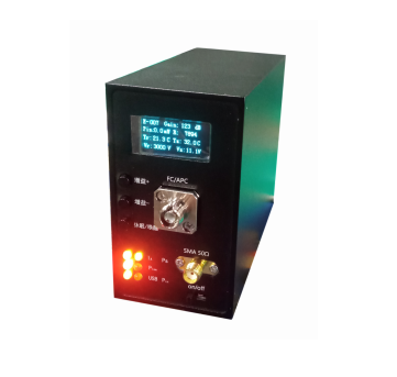
Rof DTS series 3G analog photoelectric receiver RF over fiber link ROF Links
Product feature
analog photoelectric receiverWorking wavelength: 1310nm
Operating bandwidth: 300Hz (ultra-low frequency) ~3GHz
(We also have a type of 10KHz~6GHz)
Low noise, high gain
Automatic compensation for optical link insertion loss
With digital communication, charging, PC control and other functions
Gain 800 to 850 V/W
Application
Optical pulse signal detection
Broadband analog optical signal reception
parameters
| Parameter | Symbol | Unit | Min | Typ | Max | remark | |
| Operating wavelength | simulate |
λ1 |
nm |
1100 |
1310 |
1650 |
|
| communication |
λ2 |
nm |
1490/1550 |
One receive, one transmit |
|||
| -3dB bandwidth |
BW |
Hz |
300 |
3G |
|||
| In-band flatness |
fL |
dB |
±1 |
±1.5 |
|||
| Minimum input optical power |
Pmin |
mW |
1 |
l=1310nm |
|||
| Maximum input optical power |
Pmax |
mW |
10 |
l=1310nm |
|||
| Link gain compensation accuracy |
R |
dB |
±0.1 |
l=1310nm |
|||
| Conversion gain |
G |
V/W |
800 |
850 |
l=1310nm |
||
| Maximum output voltage swing |
Vout |
Vpp |
2 |
50Ω |
|||
| Standing wave |
S22 |
dB |
-10 |
||||
| Charging voltage |
P |
V |
DC 5 |
||||
| Charging current |
I |
A |
2 |
||||
| Input connector |
FC / APC |
||||||
| Output connector |
SMA(f) |
||||||
| Communication and charging interface |
Type C |
||||||
| Output impedance |
Z |
Ω |
50Ω |
||||
| Output coupling mode |
AC coupling |
||||||
| Dimensions (L × W × H) |
mm |
100×45×80 |
|||||
Limit Conditions
| Parameter | Symbol | Unit | Min | Typ | Max |
| Input optical power range |
Pin |
mW |
1 |
10 |
|
| Operating temperature |
Top |
ºC |
5 |
50 |
|
| Storage temperature |
Tst |
ºC |
-40 |
85 |
|
| humidness |
RH |
% |
10 |
90 |
|
| Resistance to field interference |
E |
kV/m |
20 |
Characteristic Curve
Upper Computer interface
(Example)
* The upper computer can be customized according to the actual requirements of customers (can do English interface)
Upper Computer interface
(Example)
Schematic diagram of receiver structure
1: LED display. Display information Specific information is displayed on the previous screen.
2: Function adjustment button.
The order is gain +, gain -, sleep/wake up
Sleep/Wake button: send instructions to wake up and sleep the receiver, after the receiver sleeps only E-XX sleeped.
3: Function indicator.
IA: Current indicator. When powered on, the green light indicates that the receiver is working normally.
Plow: Low optical power warning light, receiving power less than 1mW lights red.
USB: USB indicator. This indicator turns on after the USB is inserted.
PS: constant optical power indicator that blinks when the power fluctuates.
Pin: The optical power input is normal, and the received power is greater than 1mW when the red light is on.
4: Optical interface flange: FC/APC
5: RF interface: SMA
6: Power switch.
7: Communication and charging interface: Type C
order information
* please contact our seller if you have special requirements.
Rofea Optoelectronics offers a product line of commercial Electro-optic modulators, Phase modulators, Intensity modulator, Photodetectors, Laser light sources, DFB lasers,Optical amplifiers, EDFA, SLD laser, QPSK modulation, Pulse laser, Light detector, Balanced photodetector, Laser driver, Fiber optic amplifier, Optical power meter, Broadband laser, Tunable laser, Optical detector, Laser diode driver, Fiber amplifier. We also provide many particular modulators for customization, such as 1*4 array phase modulators, ultra-low Vpi, and ultra-high extinction ratio modulators, primarily used in universities and institutes.
Hope our products will be helpful to you and your research.


