Silicon photonics passive components
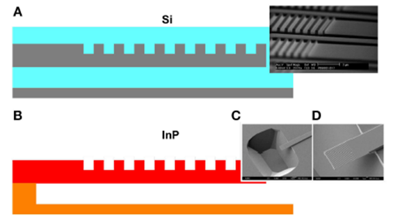
There are several key passive components in silicon photonics. One of these is a surface-emitting grating coupler, as shown in Figure 1A. It consists of a strong grating in the waveguide whose period is approximately equal to the wavelength of the light wave in the waveguide. This allows the light to be emitted or received perpendicular to the surface, making it ideal for wafer-level measurements and/or coupling to the fiber. Grating couplers are somewhat unique to silicon photonics in that they require high vertical index contrast. For example, if you try to make a grating coupler in a conventional InP waveguide, the light leaks directly into the substrate instead of being emitted vertically because the grating waveguide has a lower average refractive index than the substrate. To make it work in the InP, material must be excavated beneath the grating to suspend it, as shown in Figure 1B.

Figure 1: surface-emitting one-dimensional grating couplers in silicon (A) and InP (B). In (A), gray and light blue represent silicon and silica, respectively. In (B), red and orange represent InGaAsP and InP, respectively. Figures (C) and (D) are scanning electron microscope (SEM) images of an InP suspended cantilever grating coupler.
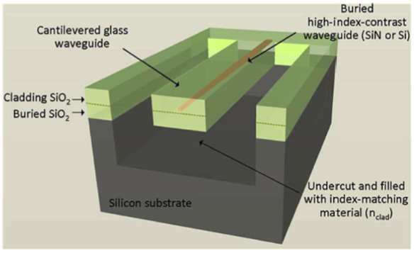
Another key component is the spot-size converter (SSC) between the optical waveguide and the fiber, which converts a mode of about 0.5 × 1 μm2 in the silicon waveguide to a mode of about 10 × 10 μm2 in the fiber. A typical approach is to use a structure called the inverse taper, in which the waveguide gradually Narrows to a small tip, which results in a significant expansion of the optical mode patch. This mode can be captured by a suspended glass waveguide, as shown in Figure 2. With such an SSC, the coupling loss of less than 1.5dB is easily achieved.

Figure 2: Pattern size converter for silicon wire waveguides. The silicon material forms an inverse conical structure inside the suspended glass waveguide. The silicon substrate has been etched away beneath the suspended glass waveguide.
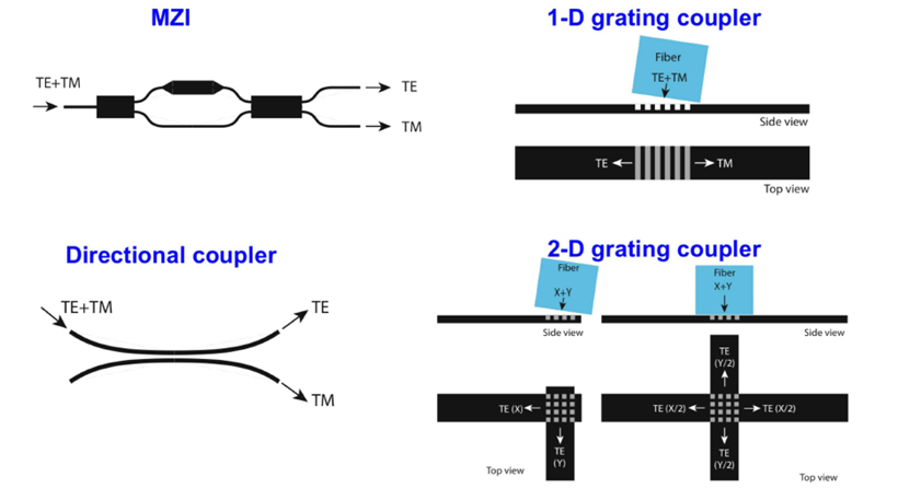
The key passive component is the polarization beam splitter. Some examples of polarization splitters are shown in Figure 3. The first is a Mach-Zender interferometer (MZI), where each arm has a different birefringence. The second is a simple directional coupler. The shape birefringence of a typical silicon wire waveguide is very high, so transverse magnetic (TM) polarized light can be fully coupled, while transverse electrical (TE) polarized light can be almost uncoupled. The third is a grating coupler, in which the fiber is placed at an Angle so that TE polarized light is coupled in one direction and TM polarized light is coupled in the other. The fourth is a two-dimensional grating coupler. Fiber modes whose electric fields are perpendicular to the direction of waveguide propagation are coupled to the corresponding waveguide. The fiber can be tilted and coupled to two waveguides, or perpendicular to the surface and coupled to four waveguides. An added advantage of two-dimensional grating couplers is that they act as polarization rotators, meaning that all light on the chip has the same polarization, but two orthogonal polarizations are used in the fiber.

Figure 3: Multiple polarization splitters.
Post time: Jul-16-2024


