ROF RF modules broadband Transceiver Module RF over fiber link Analog broadband RoF link
Description
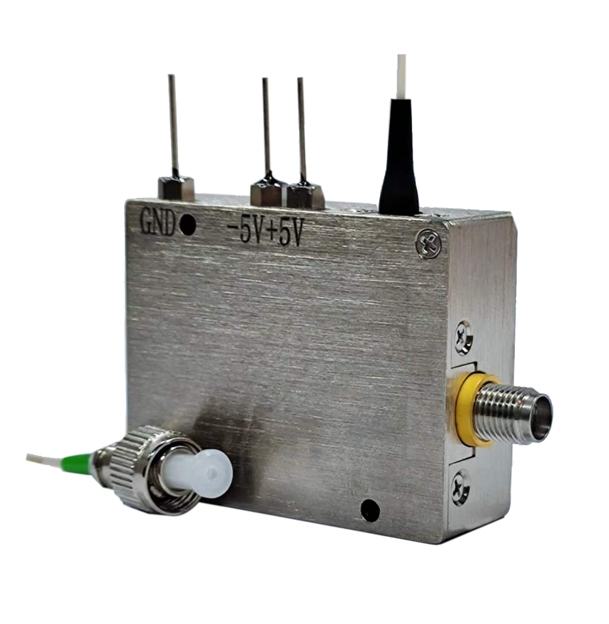
The analog RoF link is mainly composed of analog optical transmission modules and analog optical reception modules, achieving long-distance transmission of RF signals in optical fibers. The transmitting end converts the RF signal into an optical signal, which is transmitted through the optical fiber, and then the receiving end converts the optical signal into an RF signal.
Product feature
L, S, X, Ku multiple frequency terminals
Operating wavelength 1310nm/1550nm,Optional DWDM wavelength, multiplexing
Excellent RF response flatness
Wide dynamic range
Application
Remote antenna
Long distance analog fiber optic communication
Tracking, telemetry, and control(TT&C)
Satellite ground station
Electronic countermeasures
Microwave radar signal delay
parameters
performance parameters
|
Parameters |
Symbol |
Min |
Typ |
Max |
Unit |
| Wavelength |
l |
1550 |
nm |
||
| Transmitting output power |
Pop |
8 |
10 |
dBm |
|
| Transmitting side-mode-suppression |
35 |
dB |
|||
| Light isolation |
35 |
dB |
|||
| RF input frequency range * |
f |
0.1 |
18 |
GHz |
|
| RF input 1dB compression point |
P1dB |
10 |
dBm |
||
| Link gain * |
G |
0 |
2 |
dB |
|
| In-band flatness |
R |
±1 |
±1.5 |
dB |
|
| Link noise figure * |
N |
45 |
48 |
50 |
dB |
| RF output harmonic suppression ratio |
40 |
dBc |
|||
| RF output spurious suppression ratio |
80 |
dBc |
|||
| Input/output standing wave ratio |
VSWR |
1.5 |
2 |
dB |
|
| RF signal interface |
SMA |
||||
| Optical signal interface |
FC/APC |
||||
| Fiber type |
SMF |
||||
| Specifications * |
Transmitter |
Receiver |
|||
| Overall dimensions L x W x H* |
45mm*35mm*15mm |
38*17*9mm |
|||
| Power requirements * |
DC 5V |
DC ±5V |
|||
Limit parameters
|
Parameters |
Symbol |
Unit |
Min |
Typ |
Max |
| Maximum input RF power |
Pin-rf |
dBm |
20 |
||
| Maximum input optical power |
Pin-op |
dBm |
13 |
||
| Operating voltage |
U |
V |
5 |
6 |
|
| Operation temperature |
Top |
ºC |
-45 |
70 |
|
| Storage temperature |
Tst |
ºC |
-50 |
85 |
|
| Humidity |
RH |
% |
5 |
90 |
order information
| ROF | B | W | F | P | C |
| RF fiber optic transmission link | Operating Frequency:10—0.1~10GHz18—0.1~18GHz | Operating waavelength:13---1310nm15---1550nmDWDM/CWDM Please specify the wavelength, such as C33 | Fiber:S---SMF | Packaging:SS--- Transmission and reception separationMUX---Integrated transmission and reception | Connector:FP---FC/PCFA---FC/APCSP--- User Specified |
* please contact our seller if you have special requirements.
Typical Link Gain Curve
Diagram
Figure 1. Structural dimension diagram of transmission module
Figure 2. Structural dimension diagram of receiver module
Rofea Optoelectronics offers a product line of commercial Electro-optic modulators, Phase modulators, Intensity modulator, Photodetectors, Laser light sources, DFB lasers,Optical amplifiers, EDFA, SLD laser, QPSK modulation, Pulse laser, Light detector, Balanced photodetector, Laser driver, Fiber optic amplifier, Optical power meter, Broadband laser, Tunable laser, Optical detector, Laser diode driver, Fiber amplifier. We also provide many particular modulators for customization, such as 1*4 array phase modulators, ultra-low Vpi, and ultra-high extinction ratio modulators, primarily used in universities and institutes.
Hope our products will be helpful to you and your research.


