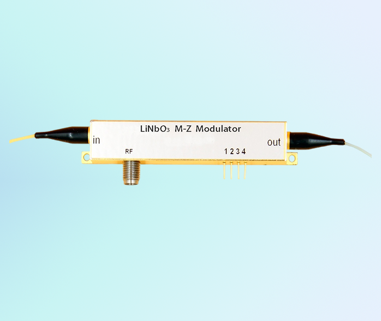
Rof Electro-optic modulator 850 nm electro optic intensity modulator 10G
Feature
Low insertion loss
Low half-voltage
High stability

Application
Space optical communication system
Cesium atomic time base
Pulse generator
Quantum Optics
Performance
Maxim DC extinction ratio
In this experiment, no RF signals were applied to the system. Pure DC extinciton has been measured.
1. Figure 5 demonstrates the optical power of modulator output, when modulator controlled at Peak point. It shows 3.71dBm in the diagram.
2. Figure 6 shows the optical power of modulator output, when modulator controlled at Null point. It shows -46.73dBm in the diagram. In real experiment, the value varies around -47dBm; and -46.73 is a stable value.
3. Therefore, the stable DC extinction ratio measured is 50.4dB.
Requirements for high extinction ratio
1. System modulator must have high extinction ratio. Characteristic of system modulator decides the maximum extinction ratio can be achieved.
2. Polarization of modulator input light shall be taken care of. Modulators are sensitive to polarization. Proper polarization can improve extinction ratio over 10dB. In lab experiments, usually a polarization controller is needed.
3. Proper bias controllers. In our DC extinction ratio experiment, 50.4dB extinction ratio has been achieved. While the datasheet of the modulator manufacture only lists 40dB. The reason of this improvement is that some modulators drift very fast. Rofea R-BC-ANY bias controllers update the bias voltage every 1 second to ensure fast track response.
Specifications
|
Parameter |
Symbol |
Min |
Typ |
Max |
Unit |
||||
| Optical parameters | |||||||||
| Operating wavelength |
l |
830 |
850 |
870 |
nm |
||||
| Insertion loss |
IL |
4.5 |
5 |
dB |
|||||
| Optical return loss |
ORL |
-45 |
dB |
||||||
| Switch extinction ratio @DC |
ER@DC |
20 |
23 |
dB |
|||||
| Dynamic extinction ratio |
DER |
13 |
dB |
||||||
| Optical fiber |
Input port |
PM780 fiber(125/250μm) |
|||||||
|
output port |
PM780 fiber(125/250μm) |
||||||||
| Optical fiber interface |
FC/PC、FC/APC Or Customization |
||||||||
| Electrical parameters | |||||||||
| Operating bandwidth (-3dB) |
S21 |
10 |
12 |
GHz |
|||||
| Half-wave voltage Vpi | RF | @1KHz |
|
2.5 |
3 |
V |
|||
| Bias | @1KHz |
|
3 |
4 |
V |
||||
| Electrical return loss |
S11 |
-12 |
-10 |
dB |
|||||
| Input impedance | RF |
ZRF |
50 |
W |
|||||
| Bias |
ZBIAS |
1M |
W |
||||||
| Electrical interface |
SMA(f) |
||||||||
Limit Conditions
|
Parameter |
Symbol |
Unit |
Min |
Typ |
Max |
| Input optical power@850nm |
Pin,Max |
dBm |
10 |
||
| Input RF power |
dBm |
28 |
|||
| bias voltage |
Vbias |
V |
-15 |
15 |
|
| Operating temperature |
Top |
℃ |
-10 |
60 |
|
| Storage temperature |
Tst |
℃ |
-40 |
85 |
|
| Humidity |
RH |
% |
5 |
90 |
Characteristic curve
ordering information:
| Rof | AM | XX | XXG | XX | XX | XX |
| Type:
AM---Intensity Modulator |
Wavelength:
07---780nm 10---1060nm 13---1310nm 15---1550nm |
Bandwidth:
10GHz 20GHz 40GHz 50GHz
|
Monitor PD:
PD---With PD |
In-Out Fiber type:
PP---PM/PM
|
Optical connector:
FA---FC/APC FP---FC/PC SP---Customization |
please contact me if you have special requirement
Rofea Optoelectronics offers a product line of commercial Electro-optic modulators, Phase modulators, Intensity modulator, Photodetectors, Laser light sources, DFB lasers,Optical amplifiers, EDFA, SLD laser, QPSK modulation, Pulse laser, Light detector, Balanced photodetector, Laser driver, Fiber optic amplifier, Optical power meter, Broadband laser, Tunable laser, Optical detector, Laser diode driver, Fiber amplifier. We also provide many particular modulators for customization, such as 1*4 array phase modulators, ultra-low Vpi, and ultra-high extinction ratio modulators, primarily used in universities and institutes.
Hope our products will be helpful to you and your research.


